Today is “Free Comic Book Day”, and “May the Fourth” (a Star Wars Holiday). I need to make my rounds on Main Street and support a few of the business owners I know.
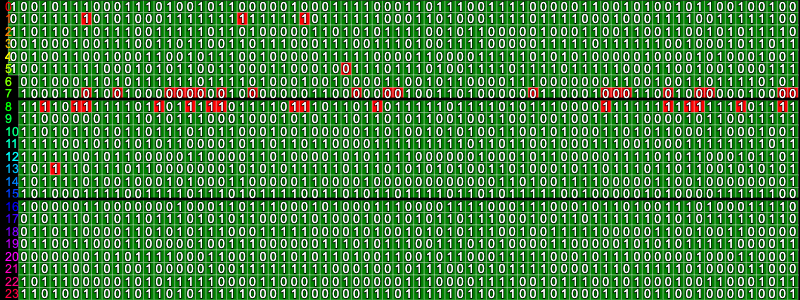
Meanwhile, I started looking at the frequencies I’m using. What I decided to do was to draw out each channels high/low band, and graph the frequency in relation to it’s current “bin”. As I reduce the FFT size, each bin covers a larger frequency range and the channels available to use are reduced in order to avoid having multiple channels fall into the same bin.
var FFT_POWER = 10;
const fftSize = 2 ** FFT_POWER;
const sampleRate = getAudioContext().sampleRate;
const frequencyResolution = sampleRate / fftSize;
function percentInFrequency(hz, frequencyResolution) {
  const index = Math.floor(hz / frequencyResolution);
  const startHz = index * frequencyResolution;
  const hzInSegement = hz - startHz;
  const percent = hzInSegement / frequencyResolution;
  return percent;
}
Here is a graph of where each channels high/low Hz falls within its frequency bin.


- Low: 5000 Hz High: 5093 Hz
- Low: 5187 Hz High: 5281 Hz
- Low: 5375 Hz High: 5468 Hz
- Low: 5562 Hz High: 5656 Hz
- Low: 5750 Hz High: 5843 Hz
- Low: 5937 Hz High: 6031 Hz
- Low: 6125 Hz High: 6218 Hz
- Low: 6312 Hz High: 6406 Hz
- Low: 6500 Hz High: 6593 Hz
- Low: 6687 Hz High: 6781 Hz
- Low: 6875 Hz High: 6968 Hz
- Low: 7062 Hz High: 7156 Hz
- Low: 7250 Hz High: 7343 Hz
- Low: 7437 Hz High: 7531 Hz
- Low: 7625 Hz High: 7718 Hz
- Low: 7812 Hz High: 7906 Hz
- Low: 8000 Hz High: 8093 Hz
- Low: 8187 Hz High: 8281 Hz
- Low: 8375 Hz High: 8468 Hz
- Low: 8562 Hz High: 8656 Hz
- Low: 8750 Hz High: 8843 Hz
- Low: 8937 Hz High: 9031 Hz
- Low: 9125 Hz High: 9218 Hz
- Low: 9312 Hz High: 9406 Hz
- Low: 9500 Hz High: 9593 Hz
- Low: 9687 Hz High: 9781 Hz
- Low: 9875 Hz High: 9968 Hz


- Low: 4590 Hz High: 4965 Hz
- Low: 5340 Hz High: 5715 Hz
- Low: 6090 Hz High: 6465 Hz
- Low: 6840 Hz High: 7215 Hz
- Low: 7590 Hz High: 7965 Hz
- Low: 8340 Hz High: 8715 Hz
- Low: 9090 Hz High: 9465 Hz
You can see that I was trying to adjust the line to be in the center of the bin, in an attempt to prevent the frequency from bleeding over into the other bins next to it. Changing the first configurations starting range to 5040 Hz did center the frequency, but I didn’t see any discernable results – so I decreased the FFT size.
It still feels like a game of cat and mouse as I dial in the frequencies that work best. For shorter segment durations, the lower FFT sizes work well with only a few channels. I found that FFT 5, resolution multiplier 2, 5,155 Hz to 15,000 Hz worked well at 10 milliseconds providing 2 channels at 200 baud.
I think my goal here will be to target as much data as I can into one second so that the audible “noise” is only in short bursts. I’ll have to setup a checksum to detect if the data was corrupted and issue a request to send the data again. For files that require multiple packets, I’ll need a way to uniquely identify the file (such as a guid), and what part of the file the packet represents. This will allow people to transfer files in smaller blocks in any order that they like. Rather than send a request for a packet to be sent again, we can wait until after all packets were received and then request the packets we want. Since the request for packets to resend individual packets could become corrupt, we would need to account for duplicate packets that we successfully received prior. Using this scheme, someone could record an audio file on a computer or cassette tape and let the receiver play it over and over again until the entire file transfers correctly. No need for back-and-forth chatter to resend individual packets.
My ideal goal would be to accomplish the 600 baud speed that my old tape cassette drive transferred data, with at least an effective baud rate of 550 bits for the data alone. Given its packets contained only 128 bytes of actual data, I think I’d like to target that size in my packets, if I can get them down to one or two seconds.
As I fiddle around with various audio spectrums, I want an easier way to determine if the error rate is failing at specific parts of the audio spectrum.
Back From Comics
I’ve been fiddling around more with the audio spectrum and found a few more signals that seem to be working out well. I’ve got eight channels at 15 milliseconds that often give a good transfer for “Hello World!” with hardly any errors to correct. It bumps the baud rate up to 600 bits per second – my main target.
| Segment Duration | 15 ms |
| Frequency | 4,000 Hz – 12,000 Hz |
| FFT Size | 2 ^ 9 |
| Frequency Resolution Multiplier | 5 |
| Baud | 600 bits/s |
| Channels | 0: 4000 Hz / 4468 Hz 1: 4937 Hz / 5406 Hz 2: 5875 Hz / 6343 Hz 3: 6812 Hz / 7281 Hz 4: 7750 Hz / 8218 Hz 5: 8687 Hz / 9156 Hz 6: 9625 Hz / 10093 Hz 7: 10562 Hz / 11031 Hz 8: 11500 Hz / 11968 Hz |
I’m rarely seeing an error, which gives me the confidence that I may be able to have packet sizes containing 128 bytes of data that can be transferred.
At this point I need a visualization to see how data is coming across individual channels, and if it is correct.

In the above graph, the channels are numbered and display a color indicating if the segment evaluated the associated bit correctly. Red is incorrect, green is correct. It appears that channels 2 and 3 are better at receiving the correct bits. I’m also seeing that at this speed, I’m only getting 2 or 3 samples per segment. Rather than counting the number of high/low wins per sample, I’m thinking about summing all the samples per segment to see if the overall amplitude of a high signal beats the low signal since a sign wave has peaks and valleys. In that case, I shouldn’t be evaluating the individual sample – but all samples within a segment.
Yes! That seems to work out much better. You can see that I have many samples with the wrong value – but the received data only has 5 bad bits. I needed the overall amplitude during the whole segment to determine which bit value wins.

With this new found logic, I think I need to highlight the whole segment rather than an individual sample. Hopefully specific frequencies will show up as being bad for transfer, or another pattern will emerge leading to more insights.
Here is another one where every bit was received just fine – but the individual samples sometimes have the wrong signals being the highest. It’s all about comparing two different wave lengths that have crest and trough out of sync with each other when the sample is acquired.

Some of the larger channels are actually working out better as well. However, I am seeing some issues as time is spread out. Here are 18 channels with 100 ms of samples. Long, drawn-out lines are not good in this situation – even when I’m summing the amplitude over time. Other things I see are vertical lines of wrong bits for just 1 sample.

These lines line up with the start/end of the segment. Something is out of synch. The Atari 410 Cassette added a mark and space between each byte. It may be that I need to stop all oscillators for 3ms between each segment before leading to the next segment so that everything can synchronize. let’s not worry about that for now. I want to see a highlight of full segments that don’t match the expected bit value that they represent.
Well… I did a bit more than just evaluate the full segments for each channel. I write the number that they evaluated to.

I wanted to match the frequencies in the graph to the bits being evaluated. I decided to assign a different color to each channel. I divided the channel index by the channel count and multiplied by 360 to assign a hue to each channel and graph. I then proceeded to assign a dotted pattern to the low signals, and make the high signals thick. For larger channel selections, I added a thick line for every eight bits to find byte values easier. I also reduced my packet size header to just 8 bits.

I still have a few questions though. Why doesn’t my low signal drop to near zero once the oscillator switches to the high signal? Why doesn’t my evaluated bits on the channels always match the evaluated bits as they are received? Both the graph and the bit receiver call the same function on the same objects to evaluate the bits. I confirmed that the data isn’t mutated by the analyzer by making a copy of what it provided to me. Something isn’t rite.
I found a configuration that seems fairly stable at the moment with a baud rate of 533.
| Segment Duration | 30ms |
| Amplitude Threshold | 75 |
| Minimum Frequency | 5,366 Hz |
| Maximum Frequency | 10,000 Hz |
| Last Segment Percent | 60% |
| FFT Size | 2 ^ 10 |
| Frequency Resolution Multiplier | 3 |
| Smoothing Time Constant | 0 |
| Hamming Code Error Correction | Yes |
What’s really wild is sending over 128 random characters and watching a graph fill up the screen. With error correction, it takes 3.4 seconds to transfer. Without, it only takes 2 seconds.

Now if you notice – the end of the data stream gets fairly corrupt in the “Received” and “Decoded” boxes. Yet – the evaluated data in the channel graph only has a few spots here and there. The data doesn’t match.
One of the things I need to consider is if I want to support “fuzzy” files. Meaning that even though the data integrity is off, most of it will be in-tact that it can be used/viewed. For example, I can show a 3D model of vectors where some of the vectors are off – but you can still make out what the 3D model is, and decide if you want to attempt to retry some of the packets, use it as-is, or discard it.
My 3D files with 1024 vertices need 3072 bytes. That doesn’t include things like a file name, author, or any other metadata. It’s just pure geometry. With the current baud rate, that would require 24 packets that would transfer in 46 seconds (1 minute and 21 seconds with error correction) – if everything transfers perfectly. It’s going to be noisy placing phones next to each other for that long. I need something faster – but it’s doable.
I was looking at the frequency ranges for long distance phone lines. They are between 300 Hz and 3.4 kHz. I plugged in a few values and tried out a stream with 128 bytes of data. Most of it got through.
| Configuration | Setting | Info | Value |
|---|---|---|---|
| Segment Duration | 30ms | Data | 128 bytes |
| Amplitude Threshold | 75 | Channels | 16 |
| Minimum Frequency | 308 Hz | Packet Bits | 1,806 |
| Maximum Frequency | 3,400 Hz | Segments | 113 |
| Last Segment Percent | 60% | Total Duration | 3.39s |
| FFT Size | 2 ^ 10 | Baud | 533.33 |
| Frequency Resolution Multiplier | 2 | Effective Baud | 304.76 |
| Smoothing Time Constant | 0 | ||
| Hamming Code Error Correction | Yes |
Just doing a bit of research on audio frequency ranges. For the most compatibility, a frequency range should be chosen between 300 Hz and 3,400 Hz if you want to support CB Radios and old telephone lines. Well… my focus is in-person, so I can skip most of the compatibility issues.
| Source | Low Hz | High Hz |
|---|---|---|
| Human Hearing | 20 | 20,000 |
| Human Vocalization | 80 | 4,000 |
| Blue Whale Vocalization | 10 | 300 |
| Humpback Whale Vocalization | 30 | 5,000 |
| Dolphin Vocalization | 20 | 100,000 |
| Dog Hearing | 40 | 65,000 |
| Dog Vocalization | 40 | 20,000 |
| AM Radio | 50 | 5,000 |
| FM Radio | 20 | 15,000 |
| CB Radio / Walkie Talkie | 300 | 3,400 |
| Cordless Phone | 300 | 3,400 |
| 88 Key Piano | 27.5 | 4,186 |
| Television / VCR | 20 | 20,000 |
| Super 8mm Film | 20 | 20,000 |
| Audio Record | 20 | 20,000 |
| Audio Cassette | 50 | 12,000 |
| Audio Compact Disc | 20 | 20,000 |
| Long/Short Distance Telephone | 300 | 3,400 |
| Atari 410 (600 baud) | 3,995 (Bit 0) | 5,327 (Bit 1) |
| Bell 103 Modem (300 baud) | 1,070 (Bit 0) | 1,270 (Bit 1) |
| Bell 202 Modem (600 baud) | 1,200 (bit 0) 1,800 (paired) | 2200 (bit 1) |

I’ve been playing around a bit more and found a 24 sets of channels that allows me to transfer 128 bytes over 800 baud without many errors.
| Configuration | Setting | Info | Value |
|---|---|---|---|
| Segment Duration | 30ms | Data | 128 bytes |
| Amplitude Threshold | 75 | Channels | 24 |
| Minimum Frequency | 304 Hz | Packet Bits | 1,806 |
| Maximum Frequency | 4,800 Hz | Segments | 76 |
| Last Segment Percent | 60% | Total Duration | 2.28s |
| FFT Size | 2 ^ 10 | Baud | 800.00 |
| Frequency Resolution Multiplier | 2 | Effective Baud | 457.14 |
| Smoothing Time Constant | 0 | ||
| Hamming Code Error Correction | Yes |
With all of this dialing in, I’m wondering if I can work that into the game. As you level up, you can add more channels, use shorter segments, and choose to add error correction. The instability of the signal, or speed is something people can work toward improving. Everyone has a base set of parameters that are almost guaranteed to work, but they can upgrade over time to improve transfer rate, error detection, and error correction. It’s up to them on how to transfer. I can start them out with smaller packet sizes too, so if they want to risk it, they can start increasing the length of the packets. And then add the ability to re-request a packet, but only if they have the ability to detect errors.
Using one channel with FSK, I can get a pretty stable result, but it takes about one minute to transfer 128 bytes with error correction at 30ms for each bit. (31 seconds without error correction). Although sometimes halfway through, the data stream is flooded with errors. I don’t know if maybe it’s a timing thing where the signal gets unstable after a few hundred microseconds.
10 to 15 seconds seems to be a failing point for now. It doesn’t seem to be a specific amount of time.
One of the other interesting things I see pop up from time to time is a specific channel has a problem more than others.

In the above example, channels seven and eight have many errors compared to the others. The frequencies are set with the following:
- Low: 304 Hz High: 397 Hz
- Low: 491 Hz High: 585 Hz
- Low: 679 Hz High: 772 Hz
- Low: 866 Hz High: 960 Hz
- Low: 1054 Hz High: 1147 Hz
- Low: 1241 Hz High: 1335 Hz
- Low: 1429 Hz High: 1522 Hz
- Low: 1616 Hz High: 1710 Hz
- Low: 1804 Hz High: 1897 Hz
- Low: 1991 Hz High: 2085 Hz
- Low: 2179 Hz High: 2272 Hz
- Low: 2366 Hz High: 2460 Hz
- Low: 2554 Hz High: 2647 Hz
- Low: 2741 Hz High: 2835 Hz
- Low: 2929 Hz High: 3022 Hz
- Low: 3116 Hz High: 3210 Hz
- Low: 3304 Hz High: 3397 Hz
- Low: 3491 Hz High: 3585 Hz
- Low: 3679 Hz High: 3772 Hz
- Low: 3866 Hz High: 3960 Hz
- Low: 4054 Hz High: 4147 Hz
- Low: 4241 Hz High: 4335 Hz
- Low: 4429 Hz High: 4522 Hz
- Low: 4616 Hz High: 4710 Hz
I suppose there is something significant about the frequencies I’ve assigned to the channels. I just don’t know what to look for. Increasing the duration up to 300 ms for each segment to capture more samples doesn’t improve the results. It feels like it’s verifying that there is an issue. Error Correction with hamming codes could fix the problem – but I have two channels sitting next to each other with this problem. If I want to help avoid groups of channels with frequency problems, I could swap a few bits between the channels so they are not sequential order, and then reverse the swap before I decode the bits. It could be as simple as moving every other bit 7 odd bits to the right, wrapping the ones that fall off the end of the channel spectrum back to the beginning. I don’t think I’m explaining that clearly. Would that help though? I could just bump them over two bits over, and increase the swap with each segment so that it’s not a solid pattern. Let me look up to see if this is even a thing. I may be thinking nonsense. The main thing is that I can’t risk having 7 bits in sequential order when two sequential channels are often failing. I can’t recover from an error with two or more incorrect bits.
Ok – so the thing I’m doing now is not only Frequency-shift keying (FSK), but also multi-frequency shift keying (MFSK). It looks like what I’m after might be frequency hopping spread spectrum (FHSS) where i would rapidly switch between multiple frequency channels with a predetermined hopping sequence. It also seems that what I am referring to as a “segment” consisting of all channel frequencies representing bits is commonly called a “symbol”.
I just realized something. Maybe my oscillators need to be square waves. None of this rolling hills of up/down. Either it’s on, or it’s off.

Maybe it’s better? It looks like less of a problem with channel 7, and channel 8 only has two bits failing.
I asked chat GPT what waveforms modems use. It listed various wave forms and how they are all used for modems, but specifically mentioned that sawtooth wave modulation is used in frequency-shift keying modulation. Let’s give it a go.
Well, I’ve run the test a few times and it seems like it’s spread out now.