I’ve been working on putting a texture on a model for two days now. I feel like I’m very close to solving it. I’m now at the point where I’m dreaming about the problem at night. Will today be the day?
Pixel to Vector
Just at the end of yesterday, I started working with some software to create some test sculpties. The main one being a cube – or as the rokuro and tatara call it, a pillar. It looks similar to a cube, but the top and bottom faces have a spider web leading to the center of the object.


Initially the software creates a pillar at a 45 degree angle. In Tatara, I was able to rotate the cube and resize it to take up the entire area. This resulted in Rokuro creating narrow cubes, and Tatara making actual cuboids with equal width, height, and depth. Now that the tatara cuboid was taking up the entire bounding box, the rendered model was cliping the back, left, and bottom faces of the sample cube that I use as a reference.


Interesting enough, the clipping does not occur with the front, right, and top faces of the cube. This is because the translation of each RGB channel value, from 0 to 255 maps to a vector from -0.5 to 0.49609375.
The technical explanation on the Second Life Wiki says that each byte value (0 to 255) is an offset from 0. Anything below 128 is a negative offset, and anything greater than 127 is a positive offset. 0 maps to -0.5 and 255 maps to 0.5. The additional note is that because a byte can not be 127.5, you can not have a vertex at the exact center of the X, Y, or Z axis of a prim.
In summary, I should have face clipping on all sides. I dug into the code that maps the value of each channel in a pixel to a vector. I had almost had the answer figured out. I just needed to increment the color value by 1 if it was 128 or more to give the impression of 257 values, but skipping 128.
| Color Value | Wrong Offset | Correct Offset |
|---|---|---|
| 0 | -0.5 | -0.5 |
| 127 | -0.00390625 | -0.00390625 |
| 128 | 0 | 0.00390625 |
| 255 | 0.49609375 | 0.5 |
Although I was getting 0.5 for my maximum color values, I wasn’t seeing any clipping. On top of that, I have an uneasy feeling about my logic. I feel as if I shouldn’t be inserting an unused value at the center.
I started looking at a previous export of my UFO to the Collada format with the Phoenix Firestorm viewer. I found the vertices and evaluated the code to find that there were only 196 unique values. Ideally, I need 256 to see all values. The values ranged from -0.4492 to 0.484314, and the closest to zero were -0.00196075 and 0.00196018. The minimum step between each value appeared to be 0.003921. In addition, they had a precision of 8 decimal points at most. Most had some long precisions, but I also found values such as -0.1, -0.3, 0.1, and 0.3.

I modified my code to cut the precision to 8 decimal points and log if the resulting value matched any of the vectors from collada. All 196 of them were not found. Either the exported collada file had the wrong values, or it was me. It’s time to upload the tatara pillar to Second Life’s asset servers and see if the Phoenix Viewer exports its edges at the max value.
Before doing that, I added the UFO model files to the current project. When revealing them in finder, I was impressed that the Collada file with the dae extension was showing up with the macOS preview. I don’t know if any 3D modeling software added an extension, or if this was native to the operating system. In addition, the model was correctly scaled and upside right within Second Life at the time that I exported it. I must refrain from making any changes to the sculpted prim before I export it.

Upload and Export
Uploading textures to an asset server costs 10 L$ (~0.031 US$). With accuracy being very important for sculpted prims, I needed to ensure the option to use Lossless Compression was checked. With the JPEG2000 format that is used, I believe there is still a potential change that the exact colors in the image could be altered when using Lossless compression. This could be why everyone paints the full image instead of just the vectors used in the model, as it may help the compression algorithm keep a group of colors together the correct value. The preview of a sculpted prim shows that the cube isn’t so crisp on the edges.


With the image uploaded, I was then able to apply it to new prim. I tried to export the object, but the COLLADA option was grayed out. I removed the wooden texture, thinking it was a permission issue since I didn’t own that specific texture. Still disabled. I then applied my own texture of the sculpted prim itself. Still disabled. What worked was deselecting the object and editing it again. I saw an option to export the UV Map. That’s going to come in handy!


Since the viewer had a preview for sculpted prims before uploading, I decided to see what my vertices looked like. All I got was a sphere. Any attempt to rotate the camera angle within the preview caused flickering. I believe this means that I’m reading the wrong values to build the model. I’ll have to come back to that at a later time.


What’s Your Vector Victor?
Time to review the exported COLLADA file. The result is that there are only 17 unique vectors for the cube ranging from -0.5 to 0.496078. I’m fascinated that the max value wasn’t 0.5. In the UFO file, deltas between each value were close to 0.003921, but mine are 0.00390625. They have a bit more distance between their vectors plotted from -0.5 to 0.5. My updated code may have vectors closer together, but vectors around the center have twice the space.
I figured it out. My original code was wrong. My original fix was wrong. The clipping on only 3 faces is fine. My steps between each value is now 0.003921569999999985.
// correct
return (byteValue / 255) - 0.5;
// wrong fix
if(byteValue >= 128) byteValue++;
// original
return (byteValue - 128) / 256;
Inspector UV
With that issue past us, let’s look at the COLLADA files UV mapping. The material has TEXCOORD that maps to a unified map array of S T values. In addition, its showing the order of vertices to be added for each face I believe within the <p> element, since the <vcount> above it is full of 3’s.

I tried to parse out all of the data and generate a UV map from it. The first attempt resulted in a UFO with a appearance like tie-dye.

All sculpted prims should have the same UV map. It’s baked into the layout of the image itself. The order of the vertices is always the same, so using the mapping from the cube should still look the same. However, the phoenix viewer could have been doing some special things under the hood when making this file. Taking a look at the cube revealed some interesting patterns. The stitching issue could still be seen between the two sides of the texture.

Our Princess Is In Another Castle
Maybe my issue isn’t with UV mapping after all. Or maybe I have my vertices or faces in the wrong order for the UV mapping in the COLLADA file to match the model that I created from the sculpted image. The COLLADA file only has 867 positions, where I’m seeing 1,089 on the web page. I believe I’m going down the wrong rabbit hole here.
I started tinkering to adjust the U value of the last column. What I found is that as I changed its value from 1 to zero, the proceeding column took on the problem with the banding. Changing it to be half way at 0.5, the two columns shared the reverse direction of the image.


I kept thinking about the values. How does the framework know that a U of 1 on the right most vertex, should match with U of 0 on the left most vertex when it wraps. Wait … that’s why its in a reverse direction for that last cell. Do I need to set something specific in my geometry to enable texture wrapping? And sure enough, there is a setting to enable it.
skin = new THREE.Texture(image);
skin.wrapS = THREE.RepeatWrapping;
skin.wrapT = THREE.RepeatWrapping;
Did it work? No. It still looked the same. When reading the documentation, it seems that this is only for how the engine handles UV coordinates that are out of range of 0 to 1. My coordinates are within range.
I keep thinking about why the texture is reversed. Sure, the value from 1 to 0 between the last two vertices would be in reverse. However, that’s why the “hidden” column of vertices was added. They take the same place as the first column. Since the two columns of vertices occupy the same space, you shouldn’t see anything.
Egg On My Face
Are we looking at the correct faces? For each vertex, I’m creating a quad to the lower right with 2 faces for each place a segment crosses – except for the top and bottom poles. The order in which the vertexes are added to define a triangle doesn’t seem to matter as long as they are added counterclockwise.
// Add triangles in counter-clockwise order
if(y === 0) {
  // triangles at top pole
  indexedTriangles.push(centerIndex, bottomIndex, bottomRightIndex);
} else if(y === verticalSegments - 1) {
  // triangles at bottom pole
  indexedTriangles.push(centerIndex, bottomRightIndex, rightIndex);
} else {
  // quads in the middle of poles
  indexedTriangles.push(centerIndex, bottomRightIndex, rightIndex);
  indexedTriangles.push(centerIndex, bottomIndex, bottomRightIndex);
}
Skipping half the triangles at the poles didn’t make a difference either. The engine still adds positions to make up for it. The UV mapping isn’t at an angle, so its specifically an issue with the “U” value. Modifying the U value in the first or last column of each row of vertices appears to cause issues with neighboring cells, or passing the problem to them to handle. For the cube, all 32 vertices appear along the edge, when reality, there are actually 33 vertices.

I feel like I’m going in circles, revisiting the same questions and confirmations. Why is this a problem? I added a little slider so that I could change the value of “U” on the last column of vertices on the web page. There are no possibles values for “U” that will make this work.
I got this little change to work with the last column of vertices. However, there is still the hidden column vertices. Any attempt to change the value of that column resulted in no visible changes. That is where I thought I would see the most impact to fix this problem.
I went ahead and added 33 sliders in all to represent each column, and the hidden one. The index at 32 had no impact – yet If I don’t include the uv value for the 33rd column, the texture twists – and I still have the weird column displaying the full texture in reverse.

A Few Vertices Short
Earlier I noticed that the bottom of the cube didn’t have a center pole. I started playing with the UV offsets while looking at the bottom of the cube. I noticed that everything mapped to one corner of the first set of vertices in the lower left of the dotted square.

Maybe I have a different problem after all. Maybe I’m not reading enough vertices. I’ve blacked out the vertices that were unused, but I didn’t black out everything at the poles except the center. I went ahead and did that, and updated the logic so that it would add additional vertices for each pole. The result was that my models were mostly fine except I had the original jagged edges coming back from the other day – but now with texture.


I feel like I’m walking backwards on problems I’ve already solved. At least I have my poles at the top and bottom of the models now.
No matter how many additional vertices I added for my poles (0, horizontal segment count, or more), the model was not affected. I got around to working the problem out. I cached the first vertex of a row while looping pixel data, and inserted to the end of the array of control vertices once I detected a new row of pixels were being read. Spider webs and jagged edges went away. I now have models with poles and the sculpted prim image has been updated to only show the center pixel at the top and bottom of the image that is used for the poles.

Did this fix the problem of UV mapping? Of course not! At least I’m solving smaller problems that I didn’t realize I had. Still… what a pain. The banding along the seem still exists. The poles are better. The bottom no longer has all faces going to a corner of the box. The top still has onion stalks.


I’m starting to get tired of looking at the same problem without any progress on the problem itself.
Identifying Vector Placement
Looking at the triangles, I’m only creating triangles for what you see on the model. Triangles between the last column and the hidden column are not created. Even when I added them, nothing had visually changed. Something has changed with the geometry though. If I skip setting the index with the triangles, I can now see some of the triangles appear anyway.

Looking through various documentation, I can’t find anything regarding the proper order to add vertices to the buffer geometry. There is mention about winding order, but that relates directly to how you define the triangles in a counterclockwise pattern. If the engine treated every triplet of vertices as a face, there would have been more faces making up the model. Instead it looks like it’s creating faces out of every 33 vertexes. Other models appear to be more of a jumbled mess and some of the faces are facing the opposite direction. Although it was an interesting experiment, it doesn’t seem like I’m going down the correct rabbit hole. I was hoping if I could get all of the vertices added normally, it would address the issue with the textures.
Perhaps it has to do with how normals are computed. Nope – that only affects light. The texture still looks bad.
Something is going on with this last hidden column of vertices. It exists, but isn’t affected by UV mapping. Could the problem be due to the fact that it shares the same vertices with the first column?
Just for confirmation, I changed the colors of the vertices so that I could see if the start and hidden vertex were at the same position. I nudged them a bit off of the original positions so that they wouldn’t share the same values. Sure enough, I saw a few cube faces flickering for the same space, but the positions were definitely there.

Spherical Index
Holy Smokes! Holy, of Holy Smokes! I figured it out. I’m kicking myself over this one. The problem lied in how I determined the spherical index based off the x/y coordinates, and the number of segments. I had to add an additional “1” to my horizontal segments, since I actually had an additional hidden segment to wrap the model. Without the fix, my triangles were sill wrapping from the last vertex in the row back to the first vertex. The hidden vertices were being ignored.
if(x < 0) {
  // stitch left to right
  x += horizontalSegments + 1;
} else if(x >= horizontalSegments) {
  // stitch right to left
  x -= horizontalSegments + 1;
}
Rotating Texture
Now it’s time to get back to the UFO and rotate the texture 90 degrees.
Something is wrong. It wasn’t supposed to be that easy. I had a tough time trying to rotate the texture after loading it from a GLTF file, converted from a colada file, downloaded via phoenix. I had given up the other day and just rotated the texture itself in Photoshop. Now, without any issue at all, it rotates.

My guess is that with all of the conversions going on from the original file, its UV mapping had changed. The fact that I created my own UV mapping directly tied to the position of the vertices in the image may have created an unexpected win.
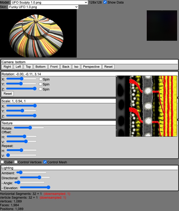
Since we are on a winning streak, I’m going to see if I can add some controls to change the textures rotation, repeat, and offset. I was always mucking with those settings in the Second Life viewer so that I could use multiple textures on different faces of an object, or different objects all together.
Texture Mapper
I February 2010, I created some desktop software with Visual Studio.net as a utility to help me figure out the different settings to be applied. It was called Texture Mapper. The end result was that you only had to pay to upload one texture instead of six in order to texture each side of a cube. The other benefit was that the Second Life viewer only had to download one texture as well, making things load faster.


From what I remember, you could drag the edges of a selection box to get the values to be applied in Second Life to only display that portion of the texture on the face of your object. I may incorporate that into my little program, as it was fairly handy at the time.
Looking at the registration code for it, it was simply an SHA hash on the avatar name and a long salted value. Security through obfuscation, I only provided a substring of the hash so that people only had 15 characters to enter. It’s currently hosted on Box.net. Feel free to download and try it out.
string name = llKey2Name(llGetOwner());
string secret = "shakE wel.l bef?ore ope''ni#Ng 163mL";
string hash = llSHA1String(name + secret);
string code = llGetSubString(hash, 4, 19);
code = llToUpper(code);
llOwnerSay("\nName: " + name + "\nSerial Number: " + code + "\nTexture Mapper: http://www.box.net/shared/035ftzyomx");
Seamless Light
I started updating the UI, grouping controls together, wiring up the cameras reset button to actually reset the camera, and displaying values of the range sliders. Github Copilot is still active and made a suggestion about adding elevation and angle to my directional lighting. I gave it a go and calculated the position. When I started playing around, I noticed the texture seam was revealed with intense lighting conditions.

I tried to enable LinearFilter as well as generate Mipmaps and change over to LinearMipmapLinearFilter for both of the textures minFilter and maxFilter settings. Nothing changed the way that light was applied. Taking it a step further, I removed the texture and saw that the problem was with the model itself.

Now it seems that I have a problem with how normals are calculated. I couldn’t get light to appear on the model until I used computeVertexNormals. Now it seems that it may not be the best choice the way that I created the geometry. The documentation for computeVertexNormals says that it computes the normals based on the faces.
As I learn more about normals, it appears that they are specific to lighting. Go figure – as that’s the main reason I added them. My model didn’t react to directional light until I computed them. I also added a call to computeTangents since that relies on both normals and uv mapping, but it did not have any discernable effects either. I have to keep reminding myself that the isn’t isn’t texture anymore, but light. The problem appears without texture as well.
Since it only appears with high-intensity directional lighting, it seems like this may be a trivial issue and that I may need to move on unless it becomes a problem.
And before I head off to bed, I added some controls to edit the texture.